GROUT : WATER STOP REINFORCEMENT OF GROUND STRATA AT MRT STATION TBM ARRIVIAL ABANDONED SHELL SECION
Confined space double-tube grouting case
1. Project Background
Grouting : A TBM was digging to the front of a diaphragm wall of a new MRT tunnel underground station.
Due to the complex ground strata conditions and the abnormal pressure of the excavation chamber, and in order to ensure safety of works on opening up the chamber for clean-up and the removal of the breakthrough face, special use of TBM abandoned shell section site improvement technology and water stop reinforcement grouting for the ground surrounding the breakthrough face.
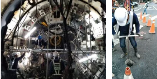
However, due to the fact that the construction of the station site had not yet been dug down to the breakthrough face level, various grouting and water testing could only be carried out inside the small TBM head, and the working conditions were extremely severe.
—
2. Solution
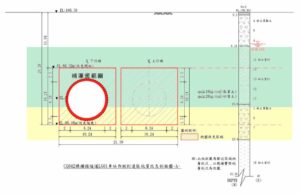
Where the breakthrough face of this project was located, about 2/3 of the thickness above was a layer of fine silt sand, and 1/3 of the thickness below was a layer of clay.There were high-pressure injected piles interspersed, and the stratum had great variability.
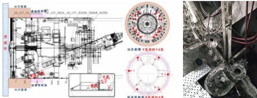
In order to avoid damaging the shield shell and causing sand and mud water to pour into the TBM, when grouting and water testing, it was planned to use the shell to inject at the Y-hole in advance for the annular oblique hole curtain grouting, and the horizontal grouting hole in front of the shell was be used as the water test inspection hole. As needed, the vertical B hole of the shell was to be used as a supplementary backfill grouting hole.
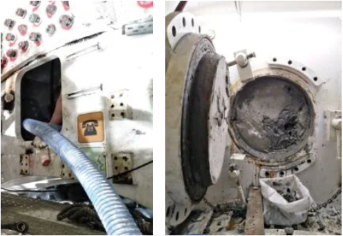
There were no grouting holes in the manhole of the upper compartment of the TBM head and the slag outlet section of the excavation chamber below.
In order to achieve a complete water-stop reinforcement effect, the upper compartment manhole position was to be reinforced by grouting the sand and soil layer using oblique hole grouting from the ground surface.
Since the lower slag outlet was located in the low-permeability clay layer, a grouting operation was not planned, and it would be decided whether or not to add supplementary grouting according to the water test results.
―
3. Works design
According to the works plan, there needed to be a range of about 3 meters outside the TBM head, and a ground improvement range with a permeability coefficient of not more than 1×10⁻⁵cm/sec.
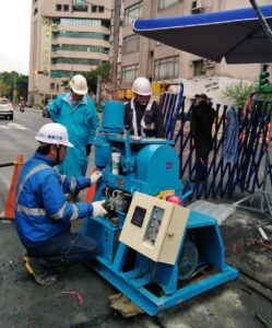
In order to achieve the goal of water stop reinforcement, and take into account the restricted space of operation, the plan was to use a miniature pneumatic hand-held drilling rig, combined with a double-tube grouting method and special small water-stop valves104825 for drilling and filling.
The grouting material selected was instant and slow-setting SSA chemical grout with good permeability, and to be used in conjunction with suspension type cement-based FLW grout. The relevant execution procedures were:
(1) Y-hole is injected with instant-solidifying SSA chemical grout to prevent the occurrence of short flow in subsequent grouting
(2) Y-hole slow-setting SSA chemical grout is injected, using the high permeability of SSA grout to fill the pores of the sandy soil layer and reduce the water permeability coefficient of the stratum
(3) Fill Y-hole with slow-setting FLW grout, using the filling and squeezing characteristics of the suspended grout, to perform local compaction and grouting of strata voids and weak zones
(4) SSA and FLW grouts to be injected into oblique holes from ground surface; there was no internal grouting hole place for the upper compartment manhole for water-stop reinforcement
(5) Water test in the horizontal grouting hole to confirm the improvement effect of the site and the permeability of the clay layer below
(6) Supplementary grouting with SSA and FLW grout materials for locations that did not reach the required water test results.
―
4. Works Process
The grouting operation of his project was mainly executed inside the TBM head.Due to the narrow operating space and working height of more than 6m, it was necessary to set up a work platform in a limited space to stand on with a pneumatic drill for diagonal drilling, installation of a water-stop valve, and double-tube reverse-stage grouting, which was more difficult.
In addition, in order to avoid damage to buried pipelines in the ground when drilling the inclined holes from the surface, it was necessary to manually excavate exploratory holes within 1.5m below the surface.
After confirming that there were no existing pipelines at the drilling position, a rotary drill was used for the double-tube grouting operation, which was extremely labor-intensive.
―
5. Results
According to the design, the grouting operation was carried out inside the TBM head, from the surface; also horizontal grouting hole water test and supplemental grouting, and then hand over to the contractor for the excavation chamber pressure test.
After strict review by industry experts, it was confirmed that the soil and water pressure met normal values.The contractor immediately opened the chamber for cleaning, then first stage of breakthrough removal, welding of the break-through and welding the protective ring between the shield shells.
During this process, the water seepage from the surrounding strata was much lower than the estimated value.The task of water-stopping and reinforcement of the ground at the abandoned shell section of the MRT station arrival was successfully achieved.
―
Water Inrush Stop Hot Bitumen Grouting Technology For Sedimentary Soil Layer Excavation Site
將下載檔案寄至:
・More Construction Result Sharing
Contact us:+886 2769-2355
Copyright ©Jines Construction Co.,Ltd