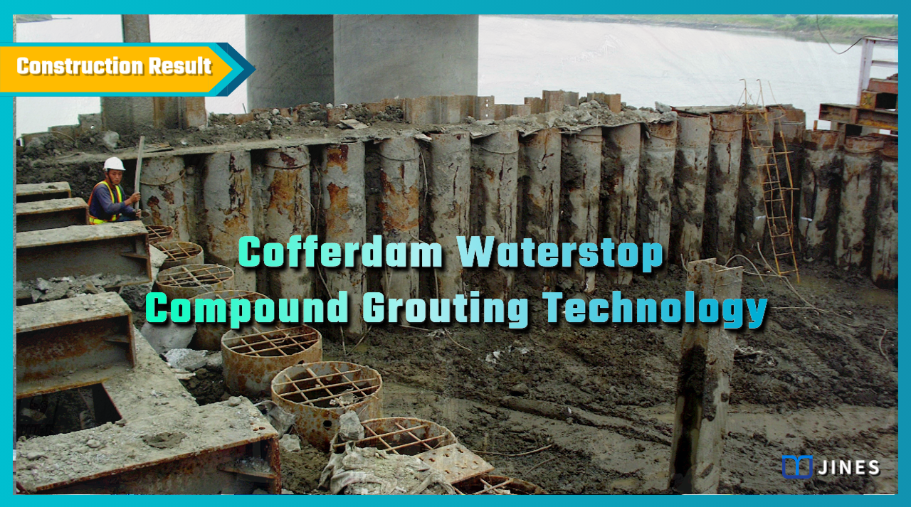
COFFERDAM WATERSTOP COMPOUND GROUTING TECHNOLOGY
Grouting to prevent water leakage into bridge foundation retaining cofferdam under construction
1. Project Background
A new bridge pier was designed with a long-span pile-raft foundation, and the foundation footing was set at a depth of about GL-21.0m below the water surface.
In order to facilitate the excavation and construction, the earth retaining facilities were designed with double layers of tenon-jointed steel pipe piles and steel sheet piles, and low-permeability clay was filled between the two to achieve the dual functions of soil and water retaining.
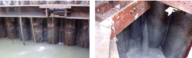
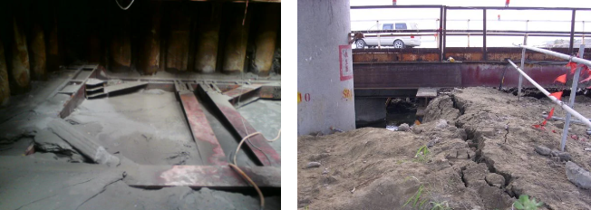
During the excavation of the foundation, a strong earthquake was encountered, which resulted in the dislocation of the steel pipe piles, resulting in serious water leakage and sand leakage.
In order to avoid continuing expansion of the disaster, the organizer used water injection to reduce the continuing influx of sand and soil, and also commissioned professional contractors to propose solutions, for implementation after the being verified.
―
2. Solution
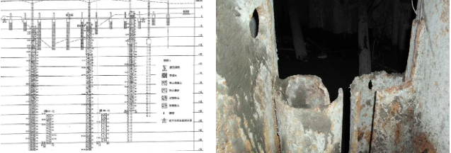
The site was located on the side of a deep trough in a river, and the geological conditions were interbeds of silty fine sand, sandy silt and clay.
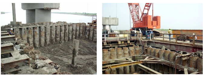
The main soil retaining facilities were tenon-jointed steel pipe piles with a length of 37m, and the gaps between tenons were filled with expanding resin to achieve the purpose of water-stopping.
However, due to the impact of the strong earthquake, many detents and expansion resin failures occurred, and the backfill clay interlayer and steel sheet piles behind it also formed local dislocations and fractures, and lost their water-retaining function.
In order to restore the water-blocking function of the deformed soil retaining facility smoothly, and at the same time avoid excessive thrust on the internal support, after evaluation, it was decided to use composite low-pressure grouting technology to repair the double-layer water-blocking function.
―
3. Works Design
Because the deformation of the retaining facilities was varied, the dislocation under the water surface was even less noticeable.
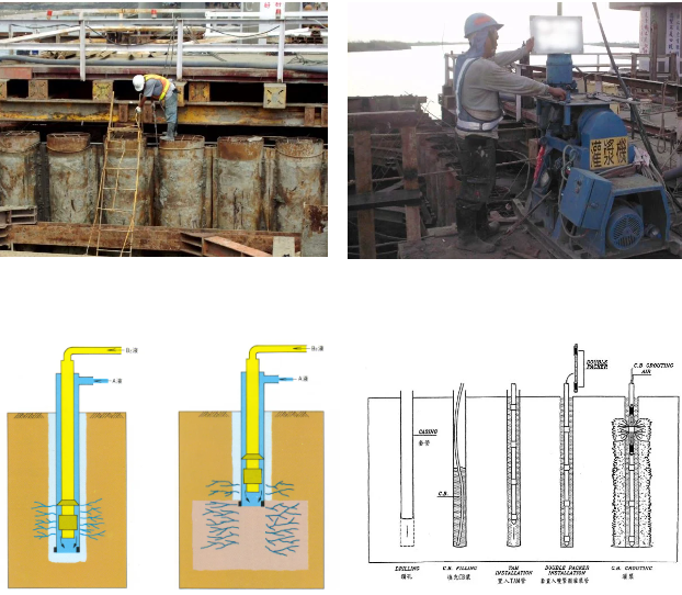
In order to achieve the water blocking effect, the grouting design was divided into 3 steps, which were as follows:
(1) Steel pipe piles surface. First fill the sand lost between the pipe piles and the steel sheet piles, and then use the double-pipe grouting method to pour the quick-setting SSA chemical grout, quick-setting FLW cement grout and the retarded SSA chemical grout on the outside of the pipe piles in three stages in sequence.
This will achieve the purpose of filling the gaps between the piles, strengthening the backfill sand and reducing the water permeability coefficient of the sand.
(2) The disturbed clay interlayer between the steel pipe piles and the steel sheet piles. The original displaced and ruptured clay layer was not uniformly mixed with the newly backfilled sand.
In order to fully restore its water blocking function, double-ring plug reverse grouting technology to be used in the interlayer, and the extrusion characteristics of CB grout used.
The disturbed and weak areas in the interlayer to be reinforced, and retarded SSA chemical grout used to fully penetrate into the sandy soil in the interlayer to form a homogeneous water-block layer.
(3) Inner leak point. After the above two grouting methods are carried out, water and influx of sand to be removed. In the process, if small-scale water seepage between the piles of not more than 20L/min is encountered, the high-expansion polyurethane resin to be used to water-stop.
In the case of large water leakage, use the embedded Marshall pipe in the interlayer at the corresponding position to supplement the grouting with localized instant-setting SSA chemical grout.
―
4. Works Process
In a short time after the earthquake, about 550 cubic meters of sand flooded into the cofferdam, and the surrounding strata and interlayer soil were very seriously disturbed, resulting in irregular flow and pressure records during initial grouting.
Later, after changing the grouting procedure to skip hole and multiple grouting methods, the grouting pressure gradually became stable.
However, due to the dislocation of the pipe piles, when the inner support was erected and pressurized, the perimeter could not be completely adhered to the pipe piles, which may have caused localized stress concentration and cause rupture to the water-blocking layer and water inrush.
The braces could not be completely fitted closely with the pipe piles, which could have caused localized stress concentration and cause the water-blocking layer to rupture and water to flow.On-site engineers were required to be on call to deal with it, and the labour needs during the construction process were slightly larger.
―
5. Results
Because the project was not far from the river’s estuary, the river water had saline-alkali characteristics.
When grouting, chemical grout and cement grout were mixed with SSA series sodium silicate matrix grout with salt and alkali resistance to ensure that all grouts will be able to solidify or hydrolyze.
After the grouting work was completed according to plan, the water inrush phenomenon on the excavation surface had completely stopped, and the small amount of water seepage on the sidewall during the excavation process was dealt with immediately by the company’s on-site engineering personnel on standby.
Bridge foundation retaining cofferdam water inrush grouting work during construction was successfully completed.
―
Cofferdam Waterstop Compound Grouting Technology
將下載檔案寄至:
・More Construction Result Sharing
Contact us:+886 2769-2355
Copyright ©Jines Construction Co.,Ltd