CONCRETE SHRINKAGE GAP CONTACT GROUTING
Compact Filling of Spaces between Machinery and Concrete Support Mounts
―
1. Project Background
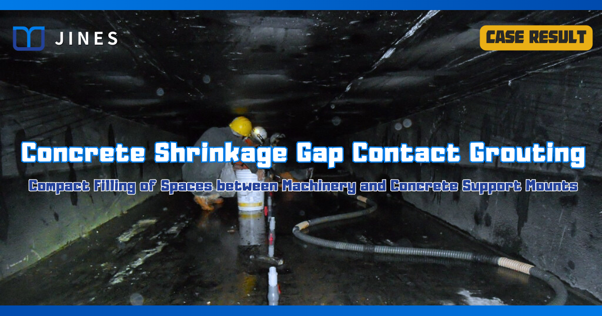
In a hydroelectric power plant, there were shrinkage gaps that had developed between the water turbine draft tube and the concrete foundation during the cement curing process.
To prevent potential damage due to vibrations or hydraulic impacts during operation, a contractor was commissioned to collaborate with maintenance personnel for on-site inspections and the development of a grouting plan. After approval, the plan was executed.
―
2. Solution
Because the location and magnitude of the shrinkage gap between the steel plate components and concrete suction outlets were not consistent, in order to fully fill all gaps between the steel suction pipes and the back of the volute in curved sections, the following plan was formulated according to the engineering characteristics:
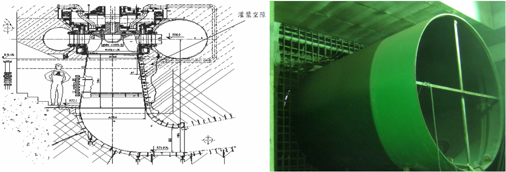
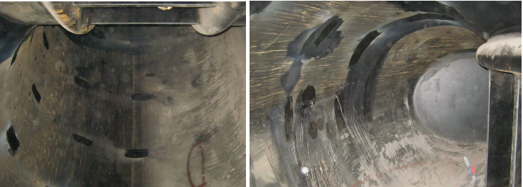
(1) Use tapping to detect gaps on the back of the steel plate;
(2) Use non-shrinkage grout to fill the gaps;
(3) Combine grouting holes with vent holes and perform dual-stage grouting from bottom to top to prevent airlocks from causing misjudgments;
(4) Use grouting pressure that can penetrate tiny shrinkage gaps but will not cause deformation of the steel plate for low-pressure grouting;
(5) After grouting each hole, it must be capable of sealing and holding pressure for curing.
―
3. Works Design
The implementation goal of this project may seem straightforward, but to ensure the proper filling of interface gaps, careful planning was required in the construction design. The main construction design was as follows:
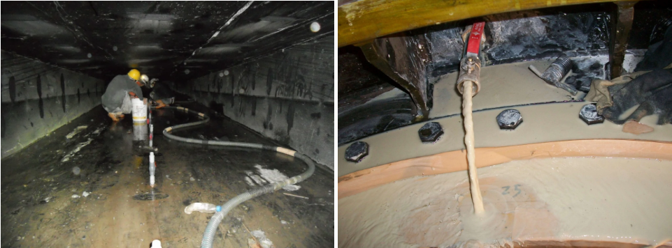
1) Use manual tapping with a wooden mallet to confirm the location and size of the gaps, and mark them on the inner steel plates of the suction pipes and volute;
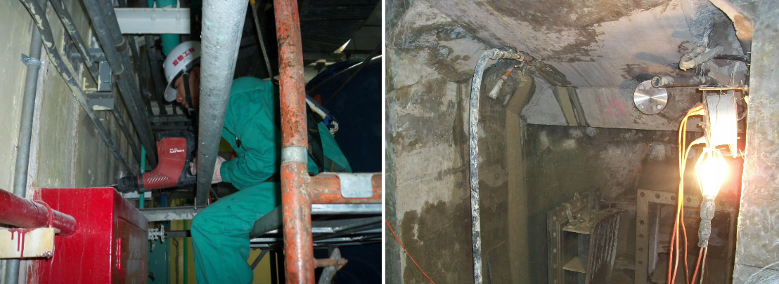
(2) For small-scale gaps, arrange a sufficient number of grouting holes and vent holes based on actual conditions;
(3) For large-scale or continuous gaps, systematic perforation is to be adopted, and the grouting holes can also serve as vent holes, with a spacing of 1.02 meters between each hole and a diameter of 30mm;
(4) Weld a pressure-holding grouting pipe with an attached sealing ball valve at each grouting hole and vent hole location;
(5) Use a non-shrinkage cement mortar suitable for filling, and based on the mixing test results, use a mix with a water content not exceeding 1.0×10⁻²cm3/cm3 within 30 minutes and a compressive strength of not less than 25MPa for the mortar specimens at 28 days;
(6) Adopt a two-stage detection and two-stage grouting method from bottom to top for segmented filling;
(7) After the second grouting and curing are completed, perform a third tapping method test to confirm the solid filling of the gaps, then remove the grouting pipes, fill the welded grouting holes, and polish for restoration.
―
4. Works Process
To achieve the desired physical properties in the mix of non-shrinkage cement mortar, it was necessary to use high-speed mixing equipment with a speed of over 300 RPM. The mixing process involved two stages: first mixing water with cement or cement grout, and then adding the expansion agent.
Additionally, to ensure the thorough filling of interface gaps during grouting, a water flow test had to be conducted before grouting began. During the grouting process, vent holes were equipped with pipes to observe any overflow, ensure there was no subsequent release of air bubbles, and checking for any lateral leakage.
Once it was confirmed that the hole was completely filled, the ball valves on the vent holes were closed, the grouting pressure was increased to 0.2MPa, and then the ball valves on the grouting holes were closed to proceed with pressure curing.
―
5. Results
In the course of this project’s grouting process, there were instances of grout leakage in certain localized areas due to lateral gaps connecting. After addressing this issue through adjustments to the non-shrinkage cement mortar mix ratio and intermittent grouting, the gaps behind the steel plates were successfully filled. Upon completion of all works, the supervising authority was notified for inspection and confirmation, and the concrete shrinkage gap contact grouting work was satisfactorily achieved.
Upon post-project review, it was found that this technique, in addition to compactly filling gaps between machinery and concrete anchor seats, can also be effectively utilized for filling gaps in secondary concrete pouring surfaces of structures or various types of discontinuous material surfaces. When combined with appropriate non-destructive testing methods, its efficiency can be further enhanced.
―
・More Construction Result Sharing
Contact us:+886 2769-2355