PREVENTIVE LEAK-STOP GROUTING AT UNDERGROUND STRUCTURE JOINTS
Deep buried Marshall Pipe double-packer waterstop grouting method
―
1. Project Background
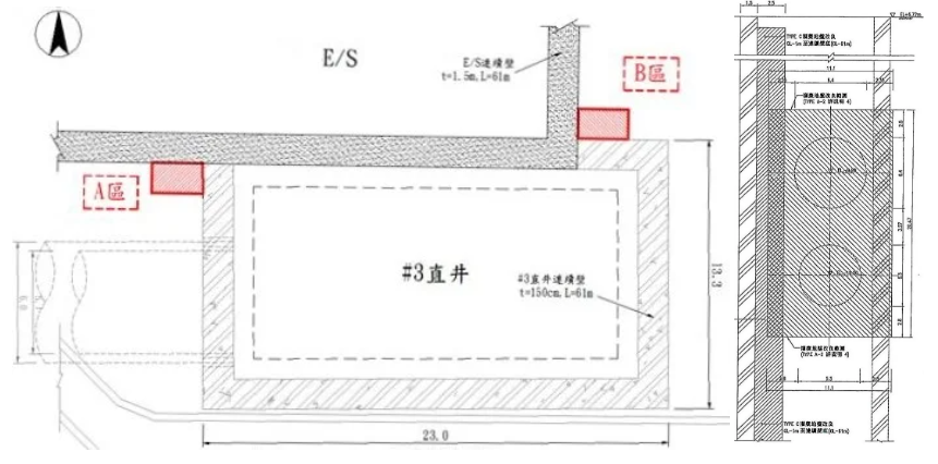
A cable tunnel project was located adjacent to a completed underground ultra-high voltage substation. Tunnel excavation was carried out using a shield driving tunneling method. One of the vertical shafts was designed with a diaphragm wall and shared a common underground space exterior wall with the substation.
To prevent any water or sand leakage issues at the junction of the diaphragm wall and the substation during the vertical shaft excavation, the construction team retained a professional contractor to perform preventive leak-stop grouting, ensuring the smooth progress of the project and preventing potential hazards.
―
2. Solution
The bottom of the vertical shaft diaphragm wall extended to a depth of GL-60m. It passed through various geological layers, including clay, silt, sand, gravel, and various interlayers, making the geological conditions quite complex.
To ensure that there is no significant leakage at the junctions of underground walls constructed at different times, the following plan was formulated based on the project’s characteristics:
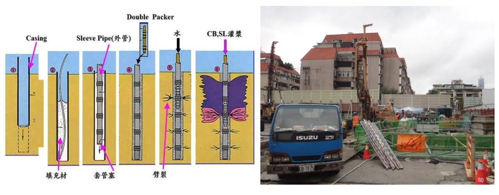
- Utilize the dual-ring seal method (sleeve pipe) for water-stop grouting, which would allow for repetitive grouting.
- During grouting, ensure the filling of voids in the strata, compression of weak zones, and groundwater sealing.
- Implement a two-stage grouting process along with irregular point injection to guarantee water-stop effectiveness.
- Flexibly control the gelation time and outlet pressure of the grout to ensure thorough coverage of the surrounding geological strata at the junctions.
- Employ large-diameter drill bores suitable for various geological conditions to install Marshall Pipes.
―
3. Works Design
Due to the significant variation in the strength and permeability of the geological layers encountered during the deep drilling in this project, many settings have to be adjusted on-site by the field engineers based on the actual conditions. The relevant construction plans were as follows:
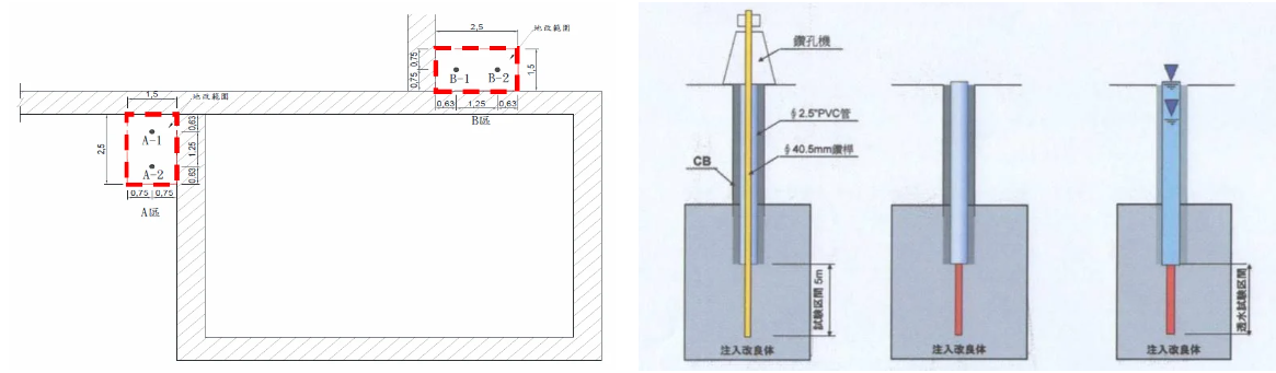
1. At two junctions of the diaphragm walls, two dual-ring seal grouting holes are planned for each junction, with grouting depths ranging from GL-1m to GL-61m. The improvement area measures 2.5m (width) × 60.0m (height) × 1.5m (length).
2. Each hole to be equipped with one Marshall Pipe, with a check valve spacing of 0.33m, and a reverse 2-stage grouting process to be employed.
3. Ground improvement injection rates are estimated at 25% for the composite layers, including 10% CB grout filling and compression of weak zones in the first stage, and 15% SSA chemical grout infiltration or fracturing strata in the second stage to reduce the permeability.
4. The SSA chemical grout is to be formulated with a 60-minute delayed setting to allow for thorough penetration into highly permeable geological layers.
5. A 118mm (OD) drill bit, along with large-diameter drill bores, is to be used with a water flushing method to minimize disturbance while drilling.
6. On-site permeability tests are to be conducted between grout holes to verify the water-stopping effectiveness. Tests are to be performed at GL-11m and GL-31m for each hole, and a geological permeability coefficient of not more than 1×10⁻⁵cm/sec will be considered as the acceptance criterion.
―
4. Works Process
In order to achieve a homogeneous geological layer and reduce the permeability of the strata while avoiding lateral deformations of the completed underground structures and diaphragm walls, the pressure setting for dual-ring seal grouting was determined as P = initial grouting pressure + 0.5~2.0 kg/cm2. This pressure setting was adjusted as needed based on the site conditions.
Additionally, due to the possibility of encountering gravel layers during drilling, which may have resulted in difficulties in splitting the outer sealing material of the Marshall pipe if the diameter was too large, the strength of the sealing material was adjusted proportionally according to the geological conditions.
―
5. Results
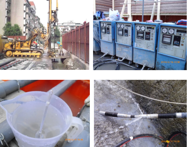
Although this project only involved the execution of four double-packer grouting holes, due to the depth of the drilling, tasks such as vertical adjustment, debris removal during drilling, proportion adjustments, and the placement of the inner pipes of the double-packers all required experienced and precise operations to achieve the best results.
After completion of the secondary grouting in the four injection holes and supplementary grouting based on abnormal pressure and flow rate depths, water permeability tests were conducted on-site according to the process records.
The test results all met the design requirements, successfully achieving the preventive leak-stop grouting at the junctions of underground structures.
―
・More Construction Result Sharing
Contact us:+886 2769-2355