TREATMENT OF WATER AND SAND INRUSH IN UNDERGROUND PASSAGE ADJACENT TO CONSTRUCTION FOUNDATION
Dual-Pipe Technique Combined with Rapid and Slow-Setting Grouts for Water Inrush Sealing
―
1. Project Background
In an underground passage near a foundation under construction, during the excavation of a diaphragm wall guide trench, an unexpected loss of stabilizing fluid occurred.
This led to water and sand inrush through secondary construction joints in the underground passage’s sidewalls and base, as well as through cracks in the earlier concrete work.
To prevent the risk of hollowing out ground and the potential damage to nearby structures, the contactor took immediate actions, including backfilling the section where stabilizing fluid was lost and conducting groundwater pumping in the underground passage.
Additionally, a professional firm was engaged to devise a ground improvement and waterproofing reinforcement plan, to facilitate the progress of subsequent construction activities. 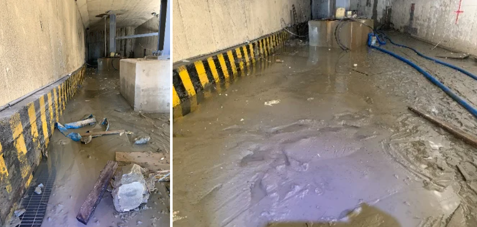
―
2. Solution
The geological conditions within the excavation depth of this project’s diaphragm wall guide trench were as follows: from ground surface to GL-4.7m, there was a layer of silty fine sand; from GL-4.7m to GL-7.1m, there was a layer of silty clay; and below GL-7.1m, there is a continuous layer of sandy silty soil.
During the excavation of the guide trench to GL-11.5m, an unexpected loss of stabilizing fluid occurred, accompanied by water and sand leakage in the underground passage. Due to the fluid loss and subsequent backfilling processes, the geological layers between the diaphragm wall and the underground passage were disturbed to varying degrees.
To reinforce the soil around the guide trench and reduce the coefficient of permeability of the layers, the following solutions were formulated:
(1) Focus the improvement efforts primarily on the area surrounding the water inrush in the underground passage and the section of the diaphragm wall guide trench where fluid loss occurred;
(2) Implement a dual-pipe grouting method with two different diameters for ground improvement, optimizing control over grout setting time;
(3) Utilize chemically reactive grout materials with low-setting strength but high waterproofing efficiency for low-pressure permeation grouting, minimizing disruption to subsequent diaphragm wall guide trench excavation;
(4) Employ long-lasting SSA chemical grout for injection, ensuring that the overall effectiveness of waterproofing throughout the project was not compromised. 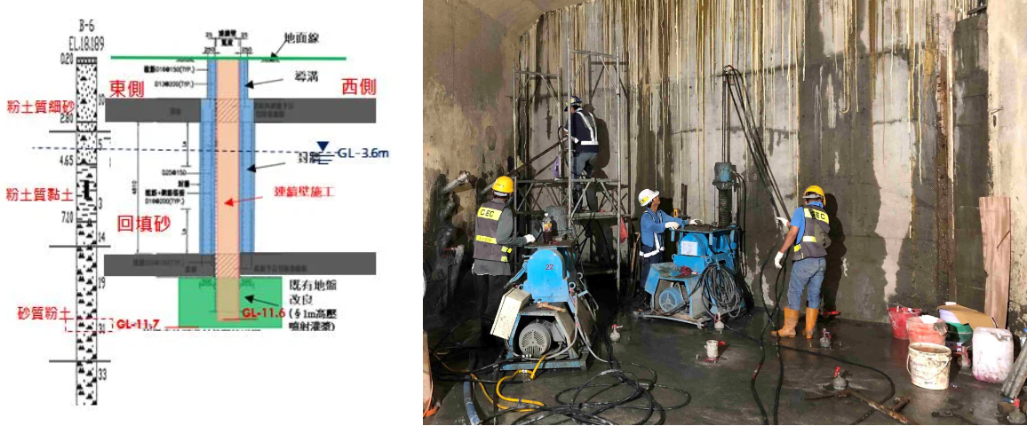
―
3. Works Design
Based on the on-site investigation, the water and sand leakage in the underground passage was found to extend approximately 20 meters, with a sand discharge volume of around 5m3. The construction design based on the solution was as follows:
1. Utilize the dual-pipe grouting method, in conjunction with long-lasting SSA chemical grout, for sealing the water inrush.
2. Apply rapid-setting sealing and slow-setting permeation grouting in an alternating manner to ensure even penetration of the grout into the sandy silty soil layer.
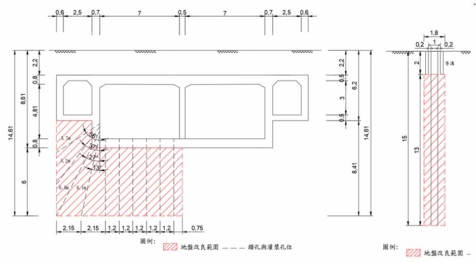
3. Employ surface drilling with reverse-stage grouting for waterproofing of the diaphragm wall guide trench, while for the surrounding layers of the underground passage, use drilling at different angles, both ascending and descending, within the underground passage.
4. The ground improvement depth was to cover from GL-2.0m to GL-15.0m for the diaphragm wall guide trench and GL-6.2m to GL-14.6m for the underground passage. This would encompass the overlying silty clay layer, the leakage location, and the lower edge of the diaphragm wall, forming a comprehensive waterproof barrier.
5. The total grouting area would be approximately 15 meters, with grout holes spaced at 1.0-meter intervals within the diaphragm wall area and 1.2-meter intervals within the interior of the underground passage.
6. After grouting is completed, the effectiveness of the grouting will be verified through on-site permeability testing.
―
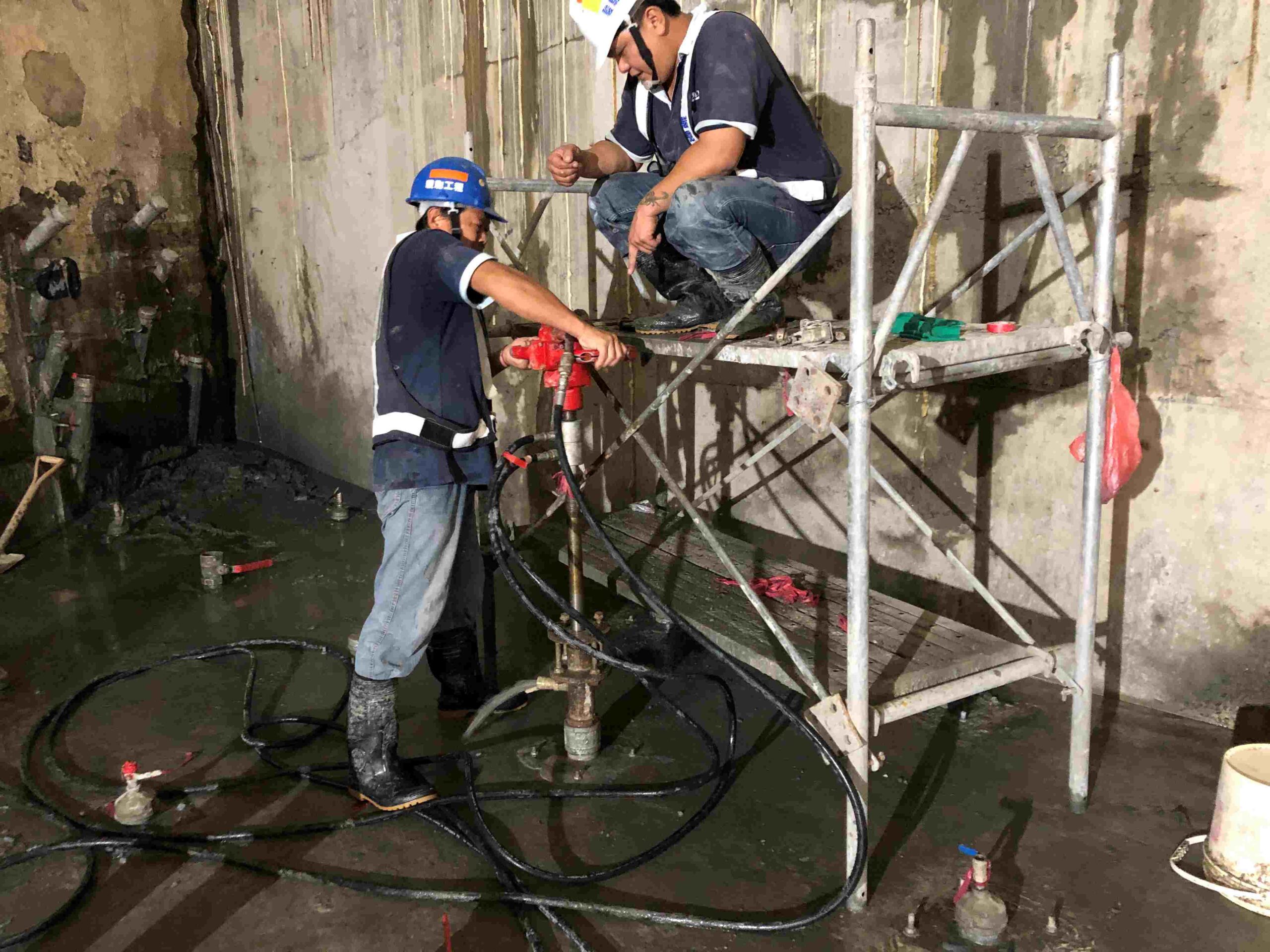
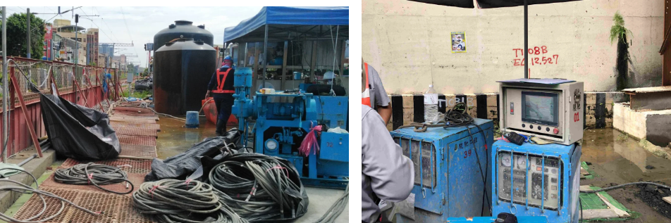
4. Works Process
Due to the impact of water and sand leakage, the geological layers between the diaphragm wall and the underground passage had been disturbed. For the dual-pipe waterproof reinforcement grouting, a stage interval of 0.5 meters was adopted, with a grout flow rate of 10 to 20 liters per minute.
This process involved using SSA low-sodium silicate chemical grout with a rapid setting time of 5 to 8 seconds and a slow setting time of 10 to 30 seconds for consolidation.
Despite being labor-intensive, time-consuming, and higher in cost, this grouting method helps mitigate secondary disturbances to the geological layers. It also results in a long-term waterproofing effect by ensuring complete and overlapping penetration of the chemical grout material.
―
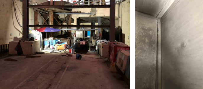
5. Results
Following the execution of grouting operations as per the construction design, effective control over water infiltration in the underground passage had been achieved.
The results of on-site permeability testing indicated that the permeability coefficient of the improved area was less than 1×10⁻⁵ cm/sec, meeting the design requirements. Subsequently, resin injection was employed to address localized concrete dampness and seepage points in the underground passage.
Furthermore, after repairing cement mortar cracks, the issue of water inrush in the underground passage has been completely resolved.
This successful intervention has led to the successful mitigation of water and sand infiltration in the underground passage adjacent to the construction site.
―
Grouting Reinforcement of Colluvial Layer at Tunnel Exit
將下載檔案寄至:
・More Construction Result Sharing
Contact us:+886 2769-2355