GROUTING : RESEVOIR COFFERDAM WATER-STOP REINFORCEMENT GROUTING CASE
Cofferdam water-stop reinforcement composite grouting technology
1. Project Background
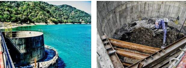
For a hydroelectric power plant to add a generator, an independent water inlet needed to be added in the reservoir.
Since the reservoir still needed to maintain its normal water storage function during the construction process, the design unit planned to construct a retaining cofferdam and retaining wall around the site.Then excavate the water inlet, construct the structure and connect the water tunnel in the cofferdam.
However, the stratum structure in the area where the cofferdam was installed was complex, and the lower rock strata were cut up and partially sandwiched by fault gouges.
In order to ensure that the cofferdam body met the requirements of high stability and low water permeability, the company was specially entrusted to coordinate the cofferdam water stop reinforcement grouting plan.

―
2. Solution
After accepting the job, the company immediately assigned professional engineers to the site to conduct detailed surveys and collect relevant topographic and stratum data.
According to the geological survey data, the thickness of the colluvial layer in this block was about 1.5-6.5m, mainly composed of brown-gray silt mixed with debris and blocks of rock.
Below it is a lightly weathered to fresh gray-black slate, having numerous joints, with fault gouge and quartz deposits in the localized fracture zone.According to the site conditions, the company proposed the following plan:
(1) Adopt quick-setting grout to water stop and reinforce the upper collapsed layer.
(2) The cracks in the lower rock pan are reinforced with slow-setting grout.
(3) The cross-section of the overall cofferdam is divided into 3 rings with staggered holes and inverse grouting.
(4) The outer ring and the inner ring are to be formed first, and the middle ring to be formed while verifying the effect in parallel with the permeation test.
(5) According to the monitoring of pressure and grouting volume changes during drilling and grouting on site, the pouring depth, grouting material types and additives can be adjusted in real time.
―
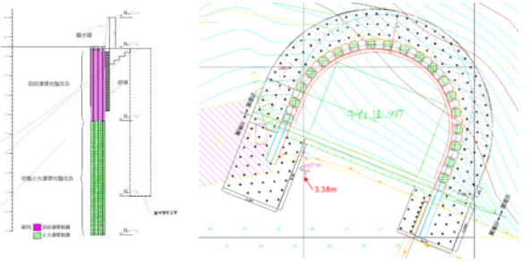
3. Works Design
According to the position of the inlet cofferdam, the grouting area is divided into cofferdam section and wingwall section.The cofferdam section is planned to extend 3.5m outward from rows of piles arranged in an arc to construct a band-shaped consolidation and water-stop screen.
The wingwall section is divided into east and west rectangular sections. An impervious screen is planned to extend deep into the strata on both sides, extend the groundwater seepage path, and reduce the impact of groundwater on the construction of the water inlet shaft.
The upper water-stop reinforcement grouting to use the double-pipe low-pressure grouting method, with quick-setting FLW grout and micro-expansive CB grout.The grouting depth is about GL±0.0m~GL-19.0m, and the depth of the weathered rock layer is at least 3m.
The grouting depth can be adjusted according to the geological conditions of the site. Cracks reinforcement grouting of the lower rock plate to use the double-ring plug method, and use for pressure grouting with retarded cement grout.Where there is a large amount of fissure water, additives can be appropriately added or the grouting material can be changed.The grouting depth is about GL-19.0m~GL-29.0m, and must be at least 10m below the bottom of the inlet shaft.
The drilling configuration uses the 1.2m hole pitch plum blossom type hole-type inverse-step grouting configuration, and it can be used with the forward-inverse stage grouting method for supplementary grouting during the second grouting phase.
The rock formation leak test (Lugeon test/Packer test) takes 5~10Lu as the evaluation standard and is carried out in accordance with the location designated by the on-site engineer.
―
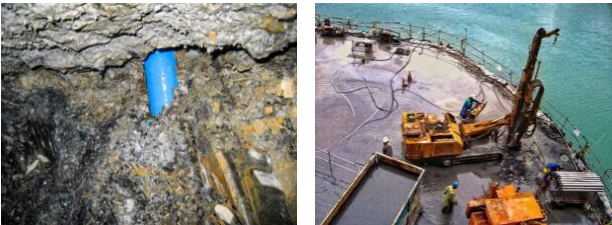
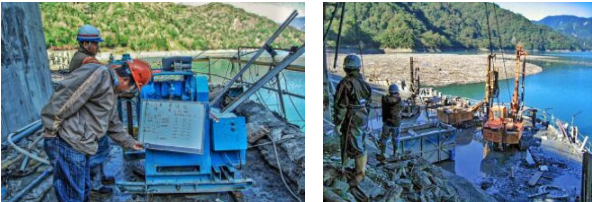
4. Works Process
During construction, in response to topography and geological conditions, large-scale drilling rigs were used for pilot holes; also buried pipes, and small drilling rigs were used for grouting.In order to prevent the grout from penetrating into the reservoir to pollute the water source during the grouting of the upper outer ring, a non-segregating additive was added to the grout as needed and the grouting pressure was adjusted immediately so that the grout would not flow into the reservoir.
When the lower part of the grouting process encountered incomplete cement grout penetration into the fine cracks of the rock formation, and the leakage test could not meet the requirements, the nano-grade silica gel cement was used for supplementary grouting to strengthen the water-stop effect.
―
5. Results
Because the works location of this project was within the reservoir area, all grout and additives had to be sampled and submitted for inspection and reported to the client for approval before they could be used.
Due to the real-time monitoring and control during the works process, there was no occurrence of grout channeling to pollute the water source.The client sent personnel to confirm that the leak-proof inspection water-stopping reinforcement met the contract requirements, and the environmental testing showed no pollution.
Their tests verified that the water-stopping reinforcement grouting work of the reservoir cofferdam had been successfully completed.
―
Reservoir Cofferdam Water-Stop Reinforcement Grouting Case
將下載檔案寄至:
・More Construction Result Sharing
Contact us:+886 2769-2355
Copyright ©Jines Construction Co.,Ltd