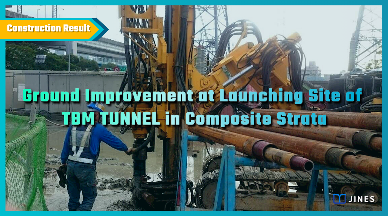
Ground Improvement at Launching Site of TBM Tunnel in Composite Strata
Integrated Ground Improvement using Full-Length Casing Piles, High-Pressure Jet Grouting, and Double-Packer Grout Injection
1. Project Background
The launching site of an underground TBM tunnel was located at a depth of GL-35.1m to GL-40.2m below the ground surface.
The upper part of the tunnel cross-section consisted of fine sand layer, while the lower part consisted of clay layer.
To ensure the smooth breakthrough and excavation at the launching site, a large-diameter full casing pile was proposed to replace the soil on the face sides.
Additionally, a water-stop grouting method was planned to prevent groundwater from inrush into the caisson shaft in case the tunnel face was breached.
These measures were implemented to ensure construction safety.
—
2. Solution
According to the geological survey report of the launching site, the interval between GL-32.6m and GL-42.7m for the installation of the full casing piles covering alternating layers of clay and fine sand.
Below this interval, there were also layers of fine sand with abundant water content and pressure-bearing characteristics, as well as layers of gravel mixed with coarse to medium sand.
To prevent soil and water inrush during construction, the proposed solution included the following measures:
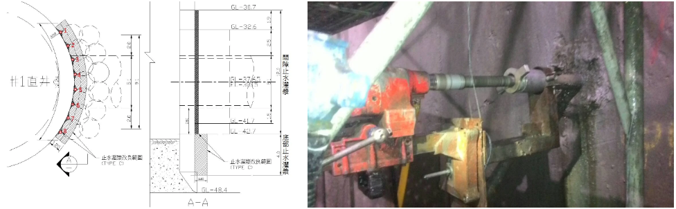
(1) Water-stop grouting between the full casing piles and caisson shaft,
(2) Water-stop grouting between the full casing piles,
(3) Water-stop grouting in the highly permeable stratum at the bottom of the full casing piles,
(4) Reinforcement and strengthening between the full casing piles and on both sides of the caisson shaft, (5) Vertical water pressure test after grouting was completed,
(6) Horizontal water pressure test before breaching the tunnel face, and
(7) Supplementary water-stop grouting.
—
3. Work Design
Based on the characteristics of the project, a composite grouting method was to be employed during the construction design, utilizing low-pressure Double-packer grouting with CB grout and SSA chemical grout to homogenize the soil and reduce permeability.
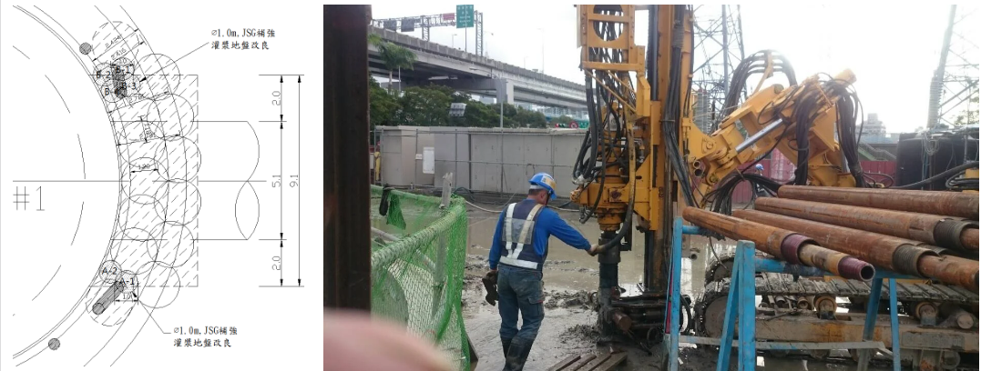
JSG high-pressure jet grouting piles, combined with water-cement ratio of 1, to be used for reinforcement on both sides to achieve ground improvement.
The implementation plan was as follows:
(1) Double-packer grouting to be carried out between the full casing piles and between the full casing piles and caisson shaft in the range of GL-30.7m to GL-42.7m.
(2) Double-packer grouting to be performed in the high-permeability stratum between GL-42.7m to GL-46.7m.
(3) JSG high-pressure jet grouting piles with an effective diameter of 1.0m to be installed on both sides of the full casing piles for water-stop reinforcement. The grouting to cover the excavation section and extend into the underlying clay layer by at least 1.2m.
(4) Vertical and horizontal permeability tests to be conducted at specified locations, depths, and quantities as directed by the owner.
(5) The coefficient of permeability must not exceed 1×10⁻⁵ cm/sec based on the results of the vertical and horizontal permeability tests.
(6) In areas where the requirements are not met, supplementary water permeability tests and water-stop grouting are to be performed.
—
4. Work Process
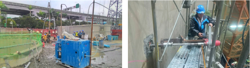
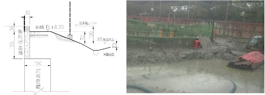
Due to the completion of the caisson shaft before the composite ground improvement, temporary retaining walls were constructed around the shaft, extending 185cm above the top of the caisson and having a width of 30cm.
This was done prior to the operation to prevent mud and water from entering the shaft during construction.
The surrounding area of the working zone was also leveled with fill soil to facilitate construction.
As the main objective of the grouting in this project was to homogenize the soil and provide ground water-stop measures, and considering that the ground improvement location was approximately between GL-30m and GL-47m below the ground surface, careful control was exercised during the hole positioning and drilling to ensure verticality.
This was done to avoid creating discontinuities in the improvement zone, which could have led to the formation of water pathways.
Furthermore, to minimize disturbance to the tunnel face and the strata, a low-pressure and low-flow-rate grouting plan was implemented.
The plan included the use of slow-setting SSA chemical grout with a gelation time of approximately 60 minutes.
The grouting was conducted with an elevation increment of 0.33m per stage, allowing the grout to thoroughly penetrate the strata and achieve soil homogenization and reduced permeability.
—
5. Results
After implementing the construction design, vertical and horizontal water permeability tests were conducted immediately.
In cases where high permeability coefficients were encountered, supplementary water testing holes were drilled at a radius of 1.0m around the affected locations.
This was done to identify potential sources of water pathways and carry out supplementary grouting.
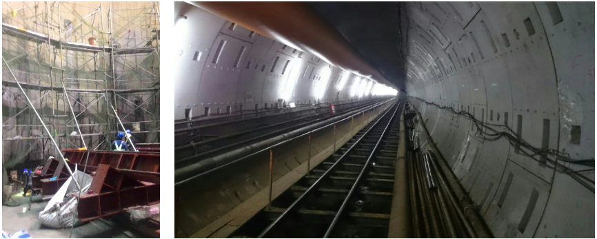
Once all the water testing activities met the required standards, the construction team proceeded according to the plan with activities such as tunnel face breakthrough, installing the face frame, and setting up the TBM tunneling equipment.
After confirming the smooth progress of the tunnel boring machine excavation, the composite ground improvement at the launching site of the TBM tunnel was successfully completed.
—
Ground Improvement at Launching Site of TBM TUNNEL in Composite Strata
將下載檔案寄至:
・More Construction Result Sharing
Contact us:+886 2769-2355
Copyright ©Jines Construction Co.,Ltd