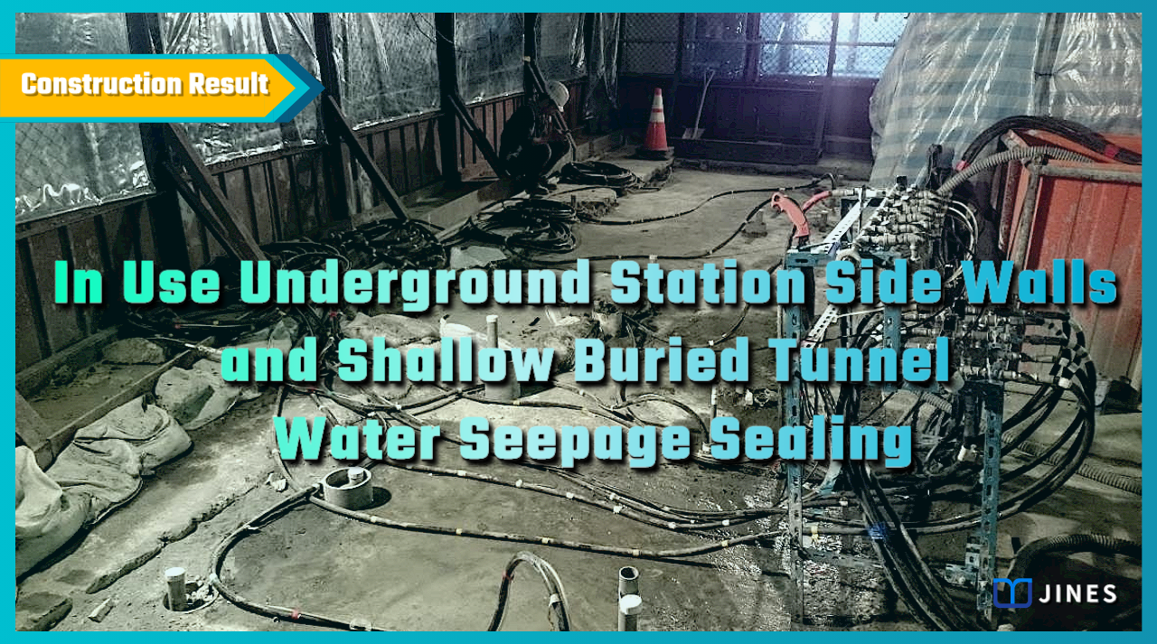
IN USE UNDERGROUND STATION SIDE WALLS AND SHALLOW BURIED TUNNEL WATER SEEPAGE SEALING
Ground improvement and repair technology for water & sand leakage in diaphragm walls expansion joints, and structural cracks.
1. Project Background
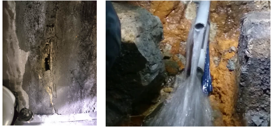
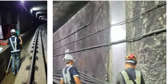
An underground MRT station and shallow-buried tunnel sidewall experienced water leakage and localized soil infiltration after operating for a period of time.
Upon inspection by the maintenance unit, it was found that the water seepage mainly occurred at the expansion joints of the diaphragm wall and some structural cracks.
In order to prevent the continuing occurrence of water and sand leakage, which could have caused harm, the supervising unit commissioned an experienced contractor to propose an improvement plan, which was approved for implementation.
―
2. Solution
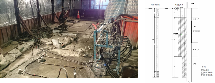
The surface below this site could be roughly classified into three layers: the backfill layer from GL ± 0.0 m to GL-2.2m, the loose to moderately dense sandy layer from GL-2.2m to GL-15.2m, and the clayey layer from GL-15.2m to GL-27.2m.
The groundwater level was approximately at GL-2.5m. Based on the site conditions, the water and sand leakage were caused by the groundwater in the second layer of sandy soil infiltrating into the underground space through the weak permeable surface of the diaphragm wall.
Considering that the MRT system could not be suspended during operation and large machinery could not be used for works in the underground space, the following solution was developed:
(1) the leakage points inside the station and tunnel to be sealed using water-guiding, resin grouting, and stainless steel plate installation methods;
(2) the Double-Packer grouting method to be used to improve the sandy soil layer outside the diaphragm wall, filling the weak zone and reducing the permeability coefficient of the ground;
(3) long-lasting cement-soil grout and SSA low-sodium sodium silicate chemical grout to be used for ground improvement;
(4) water-guiding channels to be installed in the expansion joints between the station, tunnel and the diaphragm wall to prevent groundwater from lowering in case of unexpected movements;
(5) reinforcement monitoring to be carried out on surrounding structures, surface, track, and diaphragm wall during construction. Alert value amounts, action value amounts, and contingency plans to be established.
―
3. Work Design
For the water sealing in this project, an internal waterproofing and external seepage reduction composite method to be used.
The works design to be as follows, taking into account the characteristics and requirements of the project:
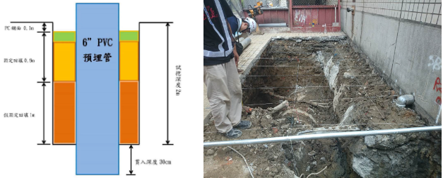
(1) Trial excavation of the road above to determine the position of the diaphragm wall and underground pipelines, and pre-embed injection pipes of 1.3m to 1.8m in length.
(2) The expansion joints of the diaphragm wall and the leakage points to be injected with polyurethane resin – expanding and non-expanding, through oblique drilling for secondary injection. After completion, the surface of cracks to be smoothed with non-shrinking cement and reinforced with stainless steel plates.
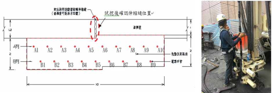
(3) The external ground improvement to use dual-row staggered Marshall tubes. The effective range of the grout to be more than 2.0m outside the diaphragm wall, and the improvement depth to reach 1.0m or more into the underlying silt clay layer.
(4) The ground improvement is to use reverse Double-Packer grouting, with a minimum injection rate of 30%. The CB grout to be mixed at a ratio of 10%, and the SSA chemical grout to be mixed at a ratio of 20%.
(5) The expansion joints between the station and the tunnel will be reinforced with resin sealing injection, and water channels to be installed on the top arch at the junctions.
―
4. Works Process
Since the remediation target was the underground MRT system, and there was a surface-level road above it, grouting inside the station and tunnel could only be carried out at night, while outside grouting adopted 24-hour operations.
Prior to construction, based on the surrounding pipeline maps and metro construction drawings, a checkerboard test excavation was performed to locate the actual position of the pipelines and diaphragm walls, and to adjust the grouting hole positions and pre-embed 6″ PVC borehole sleeves accordingly.
This ensured that the existing underground pipelines would not be damaged during future drilling and ensuring the overlapping water-stopping effect of the grout.
―
5. Results
After the internal water channeling and resin grouting were performed in this project, the water leakage at the original leaking points stopped.
Following external ground improvement, the water guide pipe no longer discharged water.
After the installation of internal stainless-steel plates and water guide channels, the application of non-shrinking cement for edge sealing, and the drilling and filling restoration, the improvement of the station and tunnel interior met the design requirements.
The water tightness level reached grade B according to the Civil Engineering Design Manual (CEDM) requirements (with damp traces on the concrete surface, but no visible water flow) or above, successfully achieving the water sealing work of the underground station and shallow buried tunnel side walls in operation.
―
In Use Underground Station Side Walls and Shallow Buried Tunnel Water Seepage Sealing
將下載檔案寄至:
・More Construction Result Sharing
Contact us:+886 2769-2355
Copyright ©Jines Construction Co.,Ltd