SITE IMPROVEMENT OF TECHNICAL BACKFILL AREA ADJACENT TO BRIDGE ABUTMENTS
Double-packer grouting for homogenization of porous granular backfill and load-bearing capacity enhancement
—
1. Project Background
In order to ensure long-term operational safety of a light rail bridge abutment, the technical backfill area at the approach section was to be filled with graded gravel. However, due to the larger voids in the backfill material adjacent to the abutment, there was a possibility of inadequate compaction and poor uniformity.
To prevent future issues such as pavement settlement, subsurface erosion, and lateral instability, the governing authority planned to implement ground improvement grouting below the approach section.
This grouting process aimed to fill the voids amongst the gravel and simultaneously strengthen the soil layers, thus ensuring the safe and reliable operation of the light rail system. 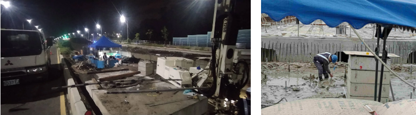
—
2. Solution
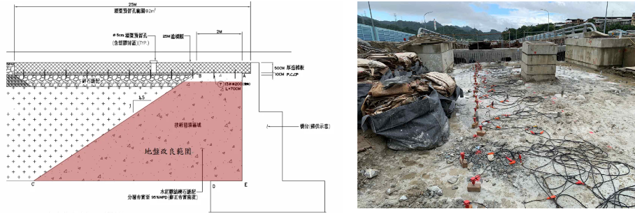
Based on the previous construction records and the results of the surface wave exploration (MASW), it was identified that the area requiring improvement exhibited a trapezoidal profile.
The maximum thickness was approximately 5.6 meters, with a length of about 12.0 meters and a width of around 6.5 meters. In accordance with the project conditions and design requirements, the following plan was proposed:
- Double-packer grouting to be employed for ground improvement.
- The grouting process to utilize the technique of Sequential Reverse-Step Grouting Method.
- Cement-bentonite grout and cement grout to be the primary grouting materials.
- The grouting holes to be arranged in an interlaced pattern.
- Upon completion of the grouting, surface wave exploration to be conducted to verify the effectiveness of the ground improvement.
—
3. Works Design
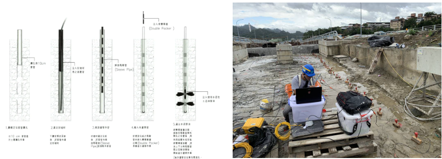
The main purpose of this grouting project was to fill the voids amongst the backfill particles, homogenize the soil layers, and enhance the soil’s load-bearing capacity. The construction design involved the use of double-packer low-pressure grouting combined with CB grout and cement grout. The relevant construction design details were as follows:
(1). The depth of each grouting hole to be 6 meters. The grouting range was divided from the bottom of the hole into sections of 0.5m, 1.5m, 2.5m, 3.5m, 4.5m, and 5.5m, with a spacing of 1.5 meters. The grouting holes to be arranged in a staggered pattern.
(2). The grouting holes were divided into 2 groups. The grouting process followed the sequence of injecting odd-numbered holes of the first group, then odd-numbered holes of the second group, then even-numbered holes of the first group, and then even-numbered holes of the second group. This ensured even distribution of the grout within the grouting range without excessive outward diffusion.
(3). During grouting, CB grout to be first used to fill the larger voids in the soil, followed by the use of pure cement grout with a water-to-cement ratio of 1:2 to penetrate the voids between the particles.
(4). The spacing between the Marshall tubes to be 0.33 meters. The flow rate of the grout to be approximately 6 to 14 L/min, and the grouting pressure to be approximately the initial pressure + 200 kPa to ensure thorough penetration of the grout into the soil layers.
(5). After completion of the grouting, surface wave exploration to be conducted to verify the effectiveness of the improvement. The corrected shear wave velocity of the improved area had to be no less than 200 m/sec after 7 days of maintenance to meet the improvement requirements.
(6). In areas where the requirements were not met, reinforcement grouting needed to be implemented. 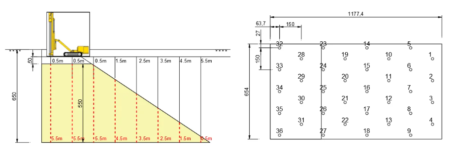
—
4. Works Process
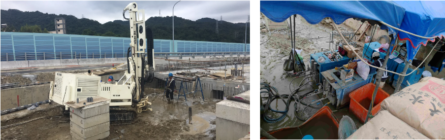
During the execution of this project, an impact drilling rig was used to bury the Marshal Pipes. Due to the larger voids in the gravel backfill layer, careful handling and proper execution of CB grouting at the borehole were necessary to prevent excessive loss of grout, which could have resulted in back-flow during subsequent grouting.
Additionally, when burying pipes in porous formations, the spread of CB grout may be wider. Therefore, it is crucial to carefully control the initial splitting time of the CB grout to ensure that the curing process does not take too long, as this could hinder the formation of the optimal grout path.
—
5. Results
After carrying out grouting and curing as per the construction design, surface wave testing was immediately conducted for verification.
Upon confirming that the corrected shear wave velocities in the improved area were all greater than 200m/sec, all records of the execution process were compiled and submitted to the supervisory authority.
The ground improvement work in the vicinity of the bridge abutment has been successfully completed. 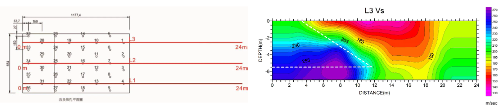
—
Site Improvement of Technical Backfill Area Adjacent to Bridge Abutments
將下載檔案寄至:
・More Construction Result Sharing
Contact us:+886 2769-2355
Copyright ©Jines Construction Co.,Ltd